- Tel: +8613911709825 /
- Email: ry@rays-casting.com /

Dual Mobility Acetabular Cup: Two Bearings Mean Two Tolerance Stacks
Dual Mobility Acetabular Cup: Two Bearings Mean Two Tolerance Stacks
A dual mobility cup hides a second bearing inside the first. A small head articulates in a mobile liner, and that liner articulates in the shell, so the implant carries two spherical interfaces where a conventional cup carries one. Buyers still quote the outer diameter as though it settled the geometry, and that habit is where most of the avoidable scrap in this product family starts. Each interface has its own sphericity, clearance and surface finish, and the two budgets add rather than average. It is also a product where a supplier can look competent on paper and still ship a shell that rattles, because the drawing described two spheres and never described their relationship. What follows is written from the machining side of the fence: where the stacks come from, which features carry them, and how we hold them without inventing inspection rules after the first article.

Acetabular Femoral Joint: Two Articulations, Two Budgets
In a native acetabular femoral joint, one cartilage surface carries the load and one clearance governs the motion. A dual mobility acetabular cup splits that role in two, and the split is what makes the tolerances interesting. The inner pair sets how the small head tracks; the outer pair sets how the liner tracks inside the shell. Both pairs are spherical, both have a designed clearance, and both must be concentric with the same centre if the liner is to stay where the designer put it. That concentricity is the specification almost nobody writes down. If the inner sphere and the outer sphere run out against each other by even a few hundredths of a millimetre, the liner migrates to one side under load, the effective clearance changes with position, and the wear path stops matching the bench data.
Acetabular Cup Dual Mobility: The Interface Between Shell and Liner
On a acetabular cup dual mobility shell, the interesting work sits at the junction rather than on the bearing. The shell carries a locking geometry that retains the liner: a taper, an anti-rotation feature, or both, depending on the design. Those features are machined after casting, and they decide whether the liner seats with the intended preload or shifts in place. Roundness at the rim matters here more than diameter, because a three-lobe rim lets the liner tilt while every diameter measurement still reads nominal. Locking groove depth and width carry their own tolerances, and a groove cut a few hundredths shallow will pass a Go gauge and still release under a pull test. Our practice is to machine the locking features on the same fixture as the outer sphere, then run a production liner through a seating trial before the lot is released, because the liner is the real gauge. The clearance band deserves a closer look, because it is the number every other feature spends. Designed clearance is usually stated as a band, and that band is consumed by everything upstream of assembly: sphericity error takes part of it, surface waviness takes more, since a wave changes the film thickness locally without changing the measured diameter, and runout between the two spheres takes the largest share because it moves the liner before load is applied. A 0.1 mm band is therefore not 0.1 mm of margin; it is 0.1 mm shared among four error sources, three of which live in the part and one in the assembly. When a buyer asks why we want runout called out separately from diameter, this is the answer.
Constrained Acetabular Component: The Retaining Ring Is a Machining Feature
A constrained acetabular component adds a third element to the stack: a ring or collar that captures the head and limits travel. That ring turns the shell into an assembly, and assemblies fail at interfaces rather than at surfaces. The ring seat is a machined feature with a flatness and a diameter, the snap feature has an undercut that has to be cut cleanly, and the removal notch has to work after the ring has been in place for years. We treat each as a capability question rather than a drawing callout. Can the seat be held flat within the stated band on a cast surface that carries its own shrinkage variation? Can the undercut be cut without burring the bearing chamfer beside it? Both answers belong in the process plan, not in a corrective action. Retention force is measured on assembled samples, and we record the assembly cycle count, because a ring that holds on the first assembly and releases on the third is a complaint waiting to happen.
3D Printed Acetabular Cup: Where Additive Hands Over to the Machine
A 3d printed acetabular cup is often presented as a finished article, which it is not. As-built surfaces from powder-bed fusion sit in the hundreds of micrometres of Ra, far from any bearing requirement, and the lattice or porous band that gives the print its advantage has no casting equivalent. So the printed route is really a hybrid: the porous fixation band is printed, and the bearing seat, the locking geometry and the rim are machined afterwards from the same part. That handover is where printed programmes lose time, because the machinist inherits a datum set created by a printer rather than by a toolmaker, and the first operation is usually spent re-establishing a centre. Cast solid shells avoid that handover entirely and hold isotropic properties through the wall, which is why they still win on cost and repeatability at production volume. The printed route earns its place on patient-specific augments and on geometries no mould can open, not on a round cup that a pattern can already make.
Dual Mobility Acetabular Cup: What Belongs on the Drawing
Six callouts do most of the work. Both sphere diameters with their individual tolerance bands, written as diameters rather than radii. The runout between the two sphere centres, referenced to one datum. Rim roundness, stated as a value rather than implied by a diameter. The locking geometry with its own gauging method. Surface finish on both bearing arcs, since a liner sees both. And the inspection method for each callout, with separate CMM zones for the inner and outer sphere, agreed before the pattern is cut. A drawing that carries all six can be quoted, tooled and inspected without a meeting; a drawing that carries three will produce a competent part and an argument. We would rather spend the argument at quotation than at first article.
Ray's Casting is a precision casting manufacturer specializing in CoCrMo (ASTM F75 / ISO 5832-4) components for orthopedic implants. Our process covers vacuum melting, precision casting, heat treatment and CNC finishing, with third-party inspection reports and full material traceability from raw material to shipment on every order.
-
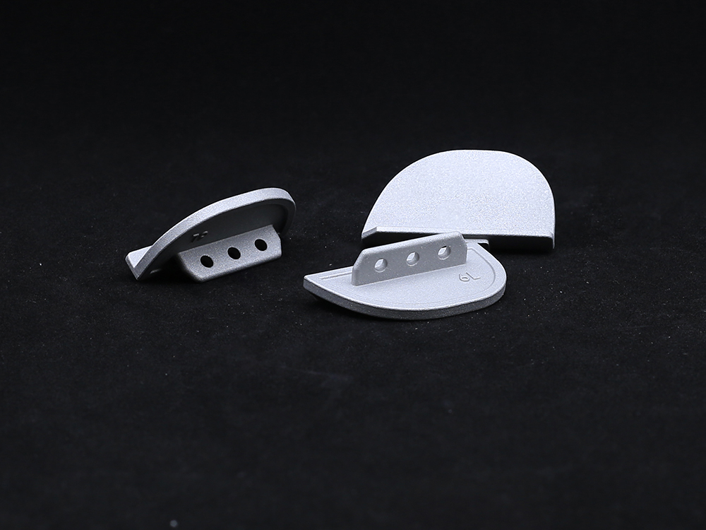 Unilateral Tibial PlateauThe unilateral tibial plateau is an orthopedic implant used in partial knee arthroplasty to replace the damaged medial or lateral tibial joint surface, thereby restoring function, relieving pain, and ensuring knee stability.
-
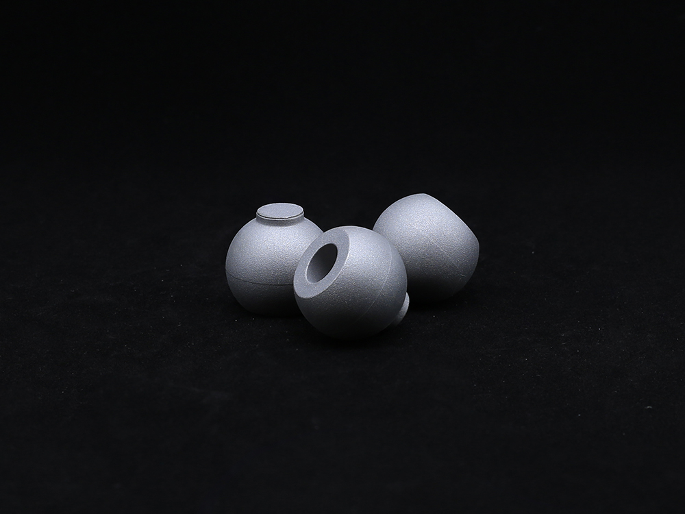 Ball HeadOur Ball Head component is designed for use in joint replacement procedures, particularly in hip and shoulder arthroplasty. Crafted from high-strength materials such as cobalt-chromium alloy or ceramic, the ball head ensures excellent wear resistance and long-term durability.
-
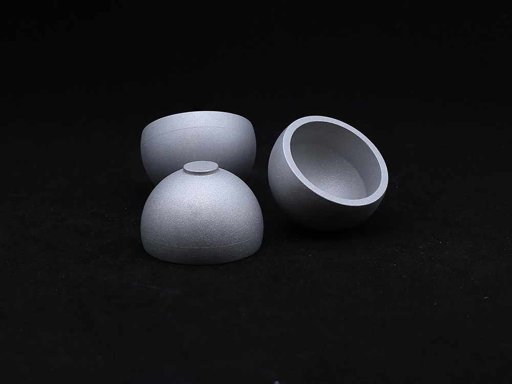 Metal CupOur Metal Cup is a critical component in hip joint replacement systems, designed to provide a durable and secure base for the acetabular implant. Manufactured from high-strength materials such as titanium alloy or cobalt-chromium, the Metal Cup offers excellent wear resistance, corrosion resistance, and long-term stability. Its anatomical design ensures proper alignment and load distribution, while its surface finish promotes optimal bone fixation.
-
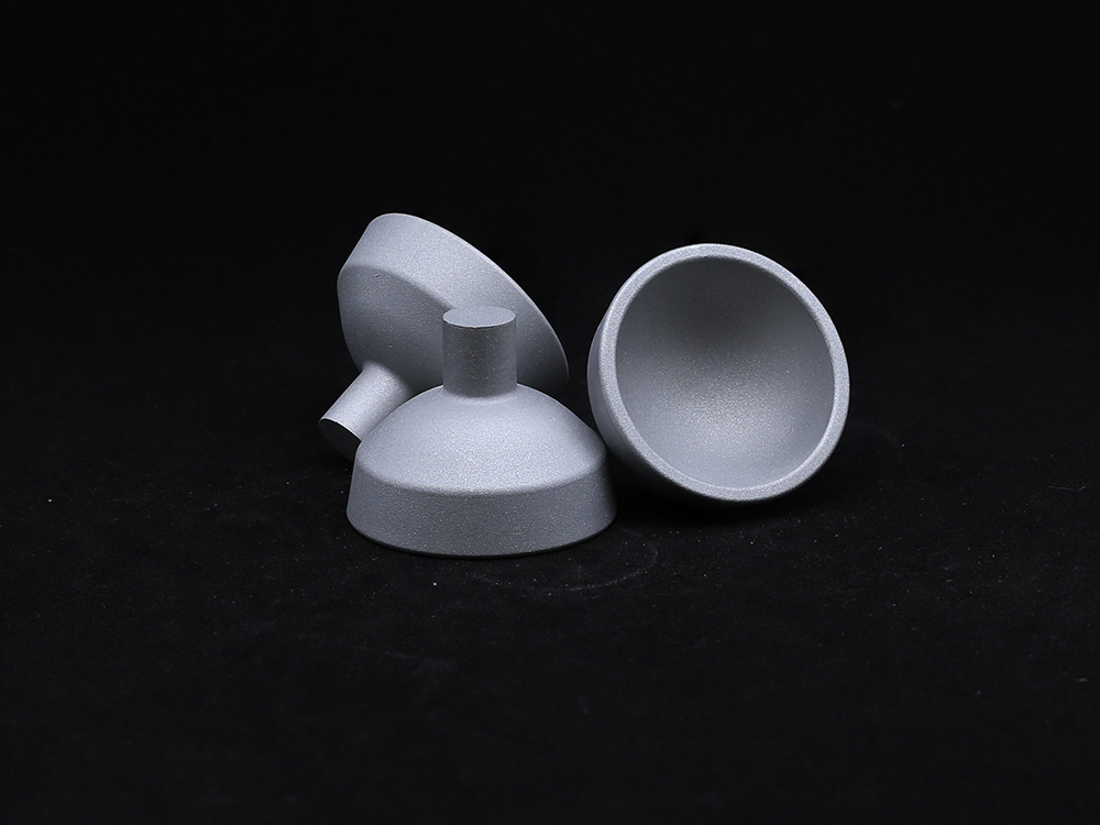 Acetabular CupMade from high-strength materials such as titanium alloy or cobalt-chromium, the Acetabular Cup ensures durability, corrosion resistance, and long-lasting performance. Its anatomical shape promotes optimal alignment and load distribution, reducing wear on bearing surfaces.
-
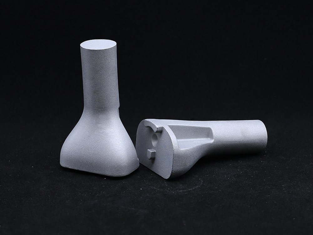 Tibial PlateauAvailable in both fixed-bearing and mobile-bearing configurations, the implants include modular baseplates and polyethylene inserts to accommodate various patient anatomies and surgical techniques.
-
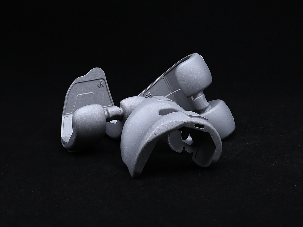 Femoral CondyleOur Half Platform system is designed to offer modular versatility in joint replacement procedures, particularly for hip and knee applications. It allows surgeons to combine components from different implant systems while maintaining biomechanical integrity and surgical efficiency.
-
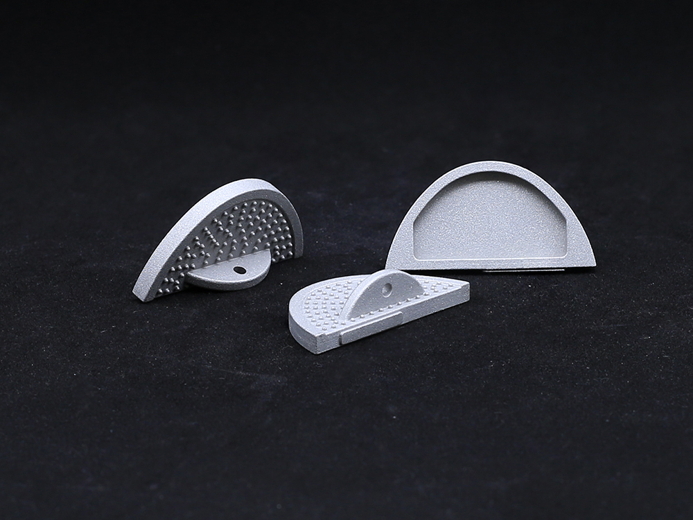 Bump Half PlatformManufactured from biocompatible, high-strength materials like titanium or cobalt-chromium alloys, it ensures durability and long-term performance. Ideal for knee, hip, or other joint replacements, the Bump Half Platform enhances surgical efficiency, minimizes inventory needs, and delivers reliable clinical outcomes with optimal joint alignment and function.
-
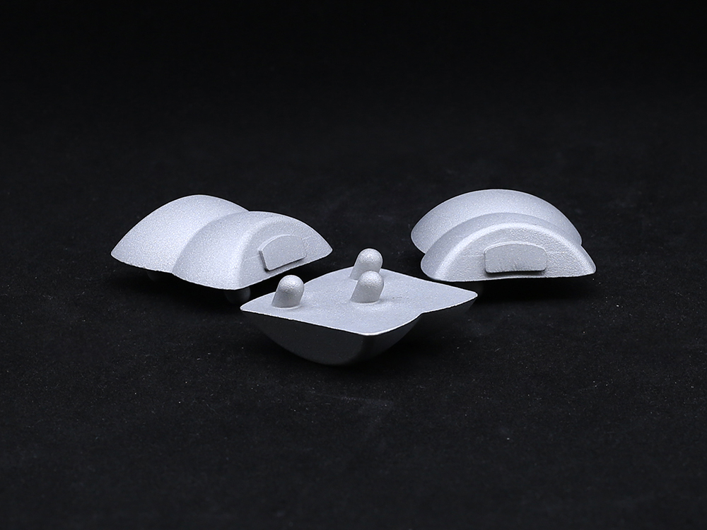 TalusTitanium alloys or PEEK materials that meet international medical standards are selected, featuring both strength and biocompatibility, effectively reducing the risk of rejection and promoting bone integration.
Get a Custom Solution!
Contact Us To Provide You With More Professional Services


