- Tel: +8613911709825 /
- Email: ry@rays-casting.com /

Ankle Component Casting: Where the Shrinkage Allowance Eats the Design Clearance
Ankle Component Casting: Where the Shrinkage Allowance Eats the Design Clearance
Ankle components are small, and that is the whole engineering problem. A linear shrinkage of one and a half per cent is a rounding error on a hundred-millimetre femoral stem. On a twenty-eight millimetre ankle feature it is four tenths of a millimetre, which happens to be the same order as the clearance the joint is designed around. Buyers tend to quote this work by weight, alloy and annual volume. A foundry has to quote it by how much of the tolerance band the furnace has already spent before the first cut is taken, and that number is not visible on any drawing. What follows looks at one ankle family from the tooling side: where the allowance goes, why form error survives machining, and when casting stops being the sensible process at all. It is worth saying early that the numbers below are typical rather than universal, because the point is not the exact percentage but the ratio between allowance and clearance on a part this size.

Ankle Synovial Joint: Where a 1.6% Allowance Turns Into a Functional Error
In an ankle synovial joint, the fluid film and the cartilage surfaces work inside a clearance measured in tenths of a millimetre. Prosthetic versions keep that logic: the bearing pair is designed with a radial clearance small enough to keep the film stable and large enough to tolerate misalignment. Casting enters the conversation because the pattern has to be made oversize by the alloy shrinkage factor, typically between 1.5 and 1.9 per cent for cobalt-chrome, and that factor is not a constant. Thin sections solidify and cool faster, so they contract less; the thicker hub of the same part contracts more. On a large component the differential is absorbed by generous machining stock. On a small ankle component it is a substantial share of the total, and it does not appear as a uniform size error that a single offset can remove. It appears as form: the sphere turns slightly barrel-shaped, the rim lifts on one side, and the wall thickness varies around the section. Machining can bring every diameter back inside its band and still leave a form error that changes the film thickness under load. Put numbers on it: a twenty-eight millimetre spherical feature at one and a half per cent grows by roughly 0.42 mm in the pattern, so the tool must remove about that much to reach nominal. If the drawing allows 0.5 mm of machining stock, the shop has 0.08 mm of margin before the part is undersize in one region and oversize in another. That is the whole argument, and it explains why ankle work is quoted with a stock analysis rather than a price per kilogram.
Ball and Socket Ankle: Thin Walls That Move Between Dewax and First Article
A ball and socket ankle component is usually the worst case for this, because the geometry demands a thin, wide shell. Walls of two to three millimetres are common, and the spherical band often spans more than a hundred degrees, which means a large unsupported area in the ceramic shell. During dewaxing the shell sees steam at pressure, and a thin shell deflects before it sets; during pour the same area is heated unevenly. The result is not a crack that inspection catches, but a slow dimensional drift that nobody looks for until the first article comes back. We measure green-state and fired-state dimensions on the first three parts of every new pattern, and we fit a sphere to the as-cast surface rather than checking three diameters. Roundness and sphere-centre position tell us where the shell moved; diameters alone hide it. Mitigation exists, and every route costs money: local shell thickness, a support core, slower ramp rates, or a gating change that feeds the thin band earlier. None of them is free, and none of them is a substitute for measuring the drift. Shell build is the place where most of the drift is set: each slurry coat and stucco layer adds thickness unevenly on a curved band, and the first coat against a thin wall is the one that decides how the shell behaves under pressure. We record coat count, slurry viscosity and drying humidity for every new pattern, because those three variables explain most of the variation between two builds of the same tool.
Ball and Socket Ankle Joint: Why Die Correction Cannot Fix a Warped Form
The instinct when a first article shows drift is to correct the die. Correction works well for size errors, because a size error is a uniform offset that the toolmaker can apply. It works badly for warp, because warp varies across the surface: adding stock on one side of the sphere removes it from the other, and the next article moves the error rather than eliminating it. We have seen programmes spend three tool iterations on a problem that a gating change solved in one. Our rule is simple: correct the die once, then change the process, then accept the deviation with a written concession if the function still holds. Chasing a warp through the pattern is how a two-month programme becomes a six-month one. The geometry of a ball and socket ankle joint rarely allows a uniform offset anyway: the spherical band, the rim and the fixation face pull in different directions as the part cools, so a single die correction is a compromise at best.
Ankle Joint Type: Batch Size Decides Whether Casting Makes Sense
Every ankle joint type carries its own tooling cost, and tooling has to be paid by somebody. A pattern, a shell build and a first article for a small ankle component can easily run to several thousand dollars before the first saleable part exists. At two hundred pieces a year that cost is trivial per unit. At thirty pieces, spread across three sizes, it can exceed the margin on the whole order. This is where a supplier earns trust by saying so. Below roughly a hundred units, machining from bar or from a forged blank is often cheaper and faster, and the geometry of most ankle components is simple enough to allow it. Above that, casting wins on stock removal time, on material yield and on repeatability, provided the shrinkage issue above has been measured rather than assumed. The honest answer changes with the buyer’s forecast, and a supplier who gives the same answer to every forecast is not really answering. Spare-parts demand makes this sharper still: a ten-year service window with unpredictable annual uptake is exactly the pattern that punishes tooling-heavy routes, while a confirmed launch volume rewards them.
Ray's Casting is a precision casting manufacturer specializing in CoCrMo (ASTM F75 / ISO 5832-4) components for orthopedic implants. Our process covers vacuum melting, precision casting, heat treatment and CNC finishing, with third-party inspection reports and full material traceability from raw material to shipment on every order.
-
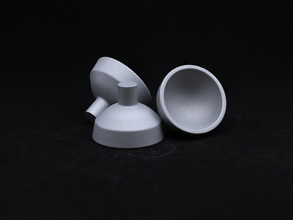 Acetabular CupMade from high-strength materials such as titanium alloy or cobalt-chromium, the Acetabular Cup ensures durability, corrosion resistance, and long-lasting performance. Its anatomical shape promotes optimal alignment and load distribution, reducing wear on bearing surfaces.
-
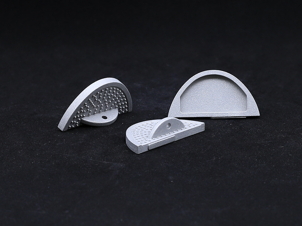 Bump Half PlatformManufactured from biocompatible, high-strength materials like titanium or cobalt-chromium alloys, it ensures durability and long-term performance. Ideal for knee, hip, or other joint replacements, the Bump Half Platform enhances surgical efficiency, minimizes inventory needs, and delivers reliable clinical outcomes with optimal joint alignment and function.
-
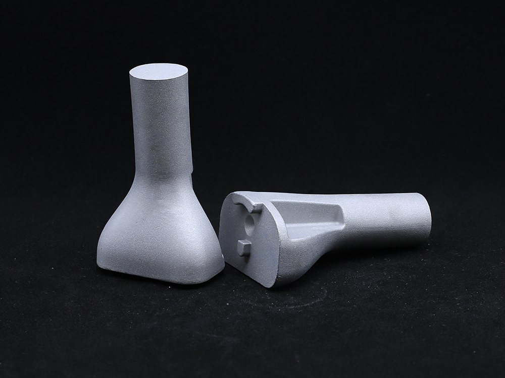 Tibial PlateauAvailable in both fixed-bearing and mobile-bearing configurations, the implants include modular baseplates and polyethylene inserts to accommodate various patient anatomies and surgical techniques.
-
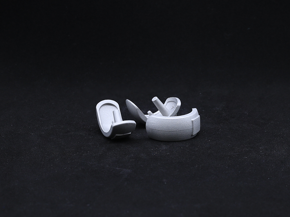 Half KneeThis minimally invasive solution preserves healthy bone, ligaments, and joint structures, enabling faster recovery and more natural knee kinematics. The system includes femoral and tibial components made from durable cobalt-chromium alloys and wear-resistant polyethylene inserts.
-
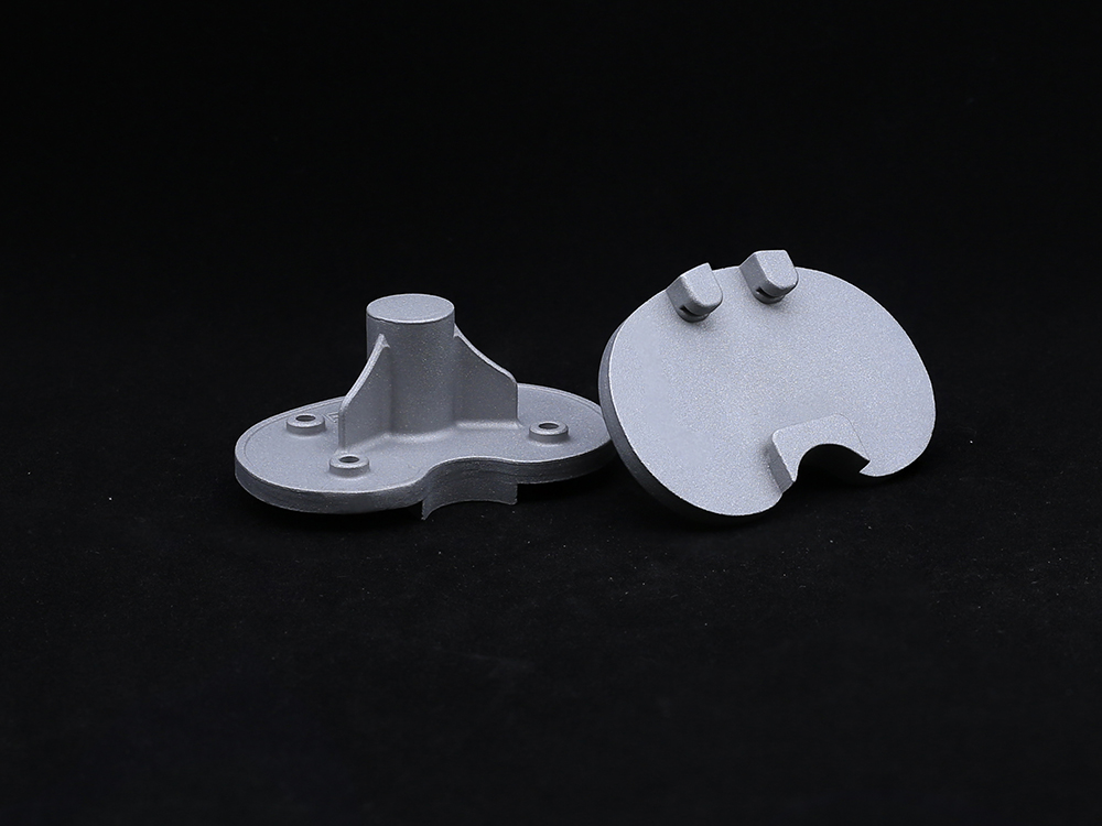 Refurbished PlatformCarefully Reprocessed To Meet The Highest Quality And Safety Standards, This Platform Is Ideal For Patients Requiring Revision Surgeries Or Those Seeking A Sustainable Option.
-
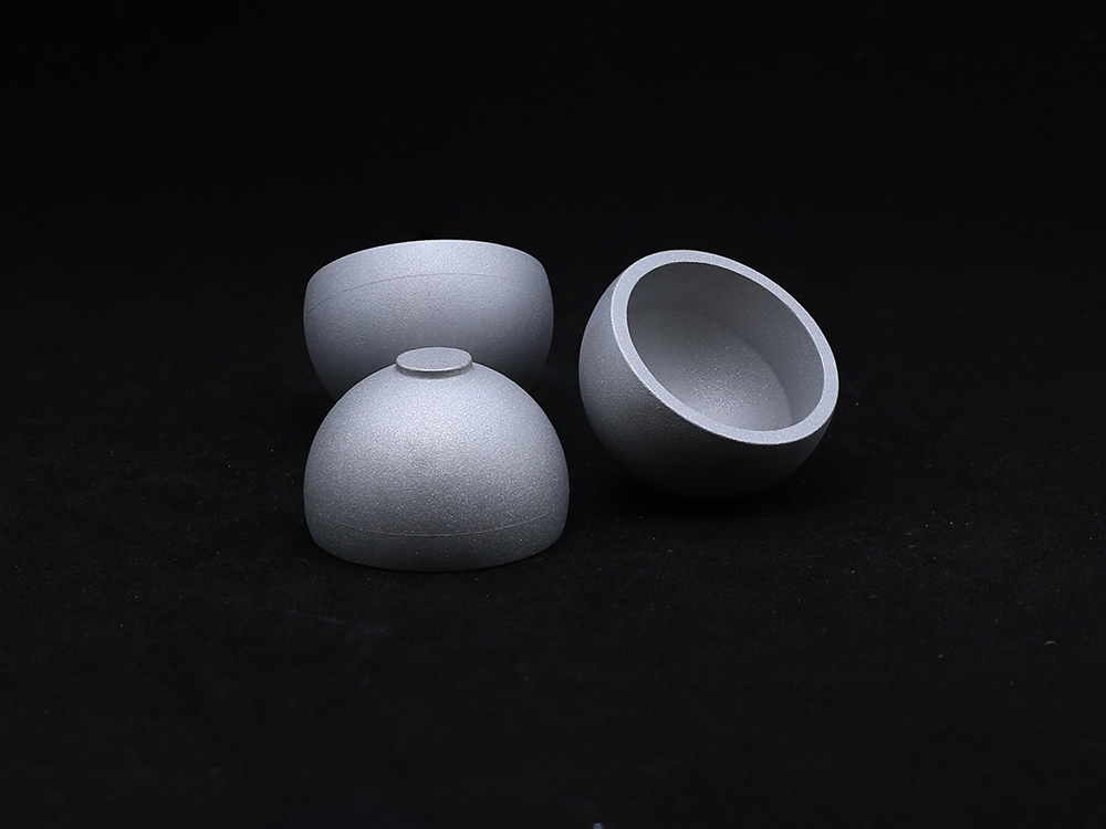 Metal CupOur Metal Cup is a critical component in hip joint replacement systems, designed to provide a durable and secure base for the acetabular implant. Manufactured from high-strength materials such as titanium alloy or cobalt-chromium, the Metal Cup offers excellent wear resistance, corrosion resistance, and long-term stability. Its anatomical design ensures proper alignment and load distribution, while its surface finish promotes optimal bone fixation.
-
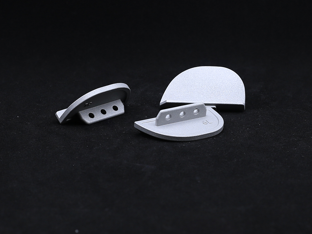 Unilateral Tibial PlateauThe unilateral tibial plateau is an orthopedic implant used in partial knee arthroplasty to replace the damaged medial or lateral tibial joint surface, thereby restoring function, relieving pain, and ensuring knee stability.
-
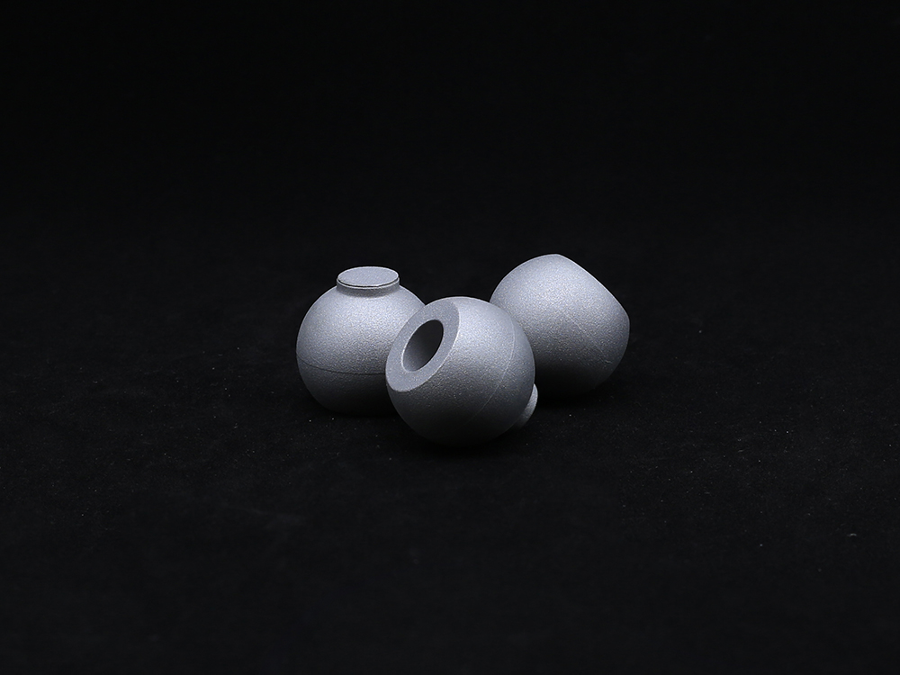 Ball HeadOur Ball Head component is designed for use in joint replacement procedures, particularly in hip and shoulder arthroplasty. Crafted from high-strength materials such as cobalt-chromium alloy or ceramic, the ball head ensures excellent wear resistance and long-term durability.
Get a Custom Solution!
Contact Us To Provide You With More Professional Services


